
The Look of Pulsed Power
The name of our company, Applied Physical Electronics L.C., says a whole lot about what we do. A typical pulsed power application relies on careful design of the physical layout and construction of a pulse generator to achieve the desired pulse specifications. While semiconductors are becoming more commonly used in pulsed power, it is still difficult, or in some cases impossible, to achieve a combination of ultra-fast rise-times (sub-nanosecond in some cases) and high peak voltages (>100kV) without the use of spark gaps, gas switches/tubes, large transformers, or pulse forming lines (i.e. very “physical” electronics). Because series inductance and stray capacitance play such a large role in achieving the desired specifications, one can almost see from a photograph the way in which the layout and components in a system give rise to a specific output waveform. For example, the distance and width of buss-work defines the impedance and/or series inductance of a system. In other cases, such as in our RS-105 Vertical EMP Simulators, the dimensions of the structure not only define the impedance, but provide insight into how the waveform propagates/radiates within the system. Because of this aspect of pulsed power, there is often an aesthetic that makes the systems both functional and incredibly captivating to look at- this is especially the case for vintage pulsed power. Before breakthroughs in dielectric materials, magnetic materials, novel switching technology, and compact system topologies, these systems were quite large (and in some cases continue to be so) with each component clearly visible.
A while back, I started a post on LinkedIn to showcase some photos our Chief Scientist, Dr. William Nunnally sent me from his days at Los Alamos. Knowing that there had to be others in our field with similar pictures, I challenged readers to send in their own photographs showcasing systems that captured the unique look of pulsed power equipment. There were some fantastic submissions that can be found here. Fortunately for us, Dr. Nunnally sent me an even larger treasure-trove of these photographs. I’m sharing them below, but will also create a follow-up post on LinkedIn for others to join in the fun.

Figure 1. Dr. Nunnally standing behind a low-inductance Marx Generator at LANL

Figure 2. A compact Marx Generator used for lightning studies
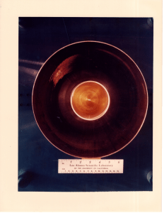
Figure 3. The business end of a plasma gun

Figure 4. High Power Engineering at LANL

Figure 5. An air-motor and alternator used to power high-voltage systems without wires

Figure 6. Not 100% sure (electron gun?), but sure looks cool!

Figure 7. Custom high-voltage probe
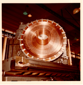
Figure 8. Half-Turn Coil

Figure 9. A thyratron-based modulator system

Figure 10. LANL Low-Inductance Marx Generator

Figure 11. LANL 1 MegAmp Transformer with 1nH Leakage

Figure 12. 12 Parallel Marx Banks

Figure 13. Dr. Henins Plasma Gun

Figure 14. Half Turn Coil 2

Figure 15. A thyratron-based modulator system (detail)