
Increased EMP Threats Lead to Changing Testing Standards
Part 2: Understanding the Standards
In our last post we highlighted the types of IEMI/EMP threats on critical infrastructure, detailing their properties and the types of damage they can cause. In order for a company, agency, utility, or community to protect against these threats, they must test their electronic equipment against various IEMI threats. Very strict military standards (MIL-STD) and their unclassified counterparts exist for developing equipment that can produce these pulses for testing.
Standards related to testing against such threats break down the threats and assign standards to individual pieces of the threat as well as the testing technology and its performance.
How the Standards Relate to the Threat
The electromagnetic threat environment can range anywhere from a high-powered microwave (HPM) device that produces extremely high peak-powers (MW to GW) in narrow-band frequency ranges (> 1GHz), to an electromagnetic pulse generated by a high-altitude nuclear event (HEMP) covering a spectrum from almost DC to the hundreds of megahertz. Given this broad spectrum and scope, it can be daunting for a test engineer to understand and apply the necessary requirements.
The first step is understanding what standards apply to the equipment under test (EUT). While the topic of electromagnetic compatibility and interference (EMI/EMC) can be even broader given the need to understand how the electromagnetic environment from both intentional and unintentional sources can affect equipment, for the purposes of this post, we will focus on intentional sources that are used in an aggressive manner and threaten civilian and military assets and lives.
To start, a test engineer should ask the following questions:
- Is my testing civilian or military?
- Am I testing a system or a subsystem?
- What threat am I testing against?
From there, the appropriate standards can be applied.
MIL-STD-464C – The Big Picture
Perhaps the most applicable standard covering EMP threats from a DoD perspective is MIL-STD-464C. As outlined in the standard, its purpose is to establish “electromagnetic environmental effects (E3) interface requirements and verification criteria for airborne, sea, space, and ground systems, including associated ordnance.”
The standard covers the impact of the entire electromagnetic environment (EME) on military systems, or what is referred to as electromagnetic environmental effects (a.k.a. E3). While the standard addresses more traditional EMI/EMC aspects, such as electronic noise emissions and self-generated RF transmissions, for the purposes of this discussion we will focus primarily on the following threat environments generated externally to the system: electromagnetic pulse (EMP), high-power microwave (HPM), and ultra-wideband (UWB).
A test engineer or manager would utilize MIL-STD-464C for guidance on the requirement rationale, but depending on the equipment or system under test, would look to several derivative standards for additional performance and testing requirements. A listing of these standards and their applicability is listed below with greater detail in subsequent blog posts:
- MIL-STD-461G: Test RS-105 in this standard details the testing of sub-systems to the unclassified E1 waveform shown in Figure 1.
- MIL-STD-188-125: Details pulse current injection (PCI) testing of fixed (MIL-STD-188-125-1) and mobile (MIL-STD-188-125-2) platforms to a separate, slower version of the E1 pulse.
- MIL-STD-3023 HEMP protection for Aircraft
- MIL-STD-4023 HEMP protection Ships
- MIL-STD-2169 Classified HEMP testing environment for systems
Electromagnetic Pulse (EMP)
MIL-STD-464C requires that a system “shall meet its operation performance after being subjected to the EMP environment.” While the actual HEMP environment is classified and defined in MIL-STD-2169, an unclassified version of the environment is provided from IEC 61000-2-9 and used in this MIL-STD.
The HEMP environment is defined in three parts: E1, E2, and E3. E1 is known as the “prompt gamma HEMP” and is the fastest portion of the pulse which couples into antennas, conducting lines, and electronic equipment. E2 is known as both the “scattered gamma” (E2a) and “neutron inelastic gamma” (E2b) HEMP waveforms. These are considerably slower pulses that couple into long power lines and VLF antennas. Lastly, E3 is the magnetohydrodynamic HEMP, and is nearly a DC field capable of coupling into long power lines and penetrating most shielding.
The E1 pulse is the most common pulse tested to, given its effect on both large and small systems as well as subsystems. The time domain plot of this pulse is shown in Figure 1. This is the same pulse detailed in test procedure RS-105 of MIL-STD-461G.
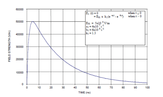
Figure 1 Unclassified free-field EMP time domain waveform for the E1 pulse (IEC 61000-2-9 and MIL-STD-464C)
Ultra-Wideband Pulse Threats
MIL-STD-464C provides very little definition for UWB other than classifying it broadly with wideband sources having a percent-bandwidth (pbw) >1%, where pbw is simply a ratio of the center frequency to the 3dB points.

Figure 2 UWB Spectrum and Time-domain example waveforms
High Power Microwave (HPM)
While MIL-STD-464C more broadly classifies HPM as including wideband sources, HPM is typically thought of as narrowband sources with a frequency >1 GHz.

Figure 3 HPM Waveform example
Solutions
Vendors serving this community must understand the threats, the standards that test or mitigate these threats, and the technology required to meet these standards. Because of the complex, technically involved nature of these sources, recreating the associated threat-level waveforms is often difficult and confined to a limited set of subject-matter experts. As a result, these devices are typically high in cost, or completely unavailable to the T&E community without significant, long lead-time investments.
Founded in 1998, Applied Physical Electronics L.C. (APELC) focuses our specialized generation of pulsed high-voltage and RF engineering expertise toward protecting against electromagnetic threats. Our unique understanding of the subject and standards, paired with our DoD contracts and extensive research and development, allows us to offer affordable threat testing technology.
APELC has focused on wideband sources after being contracted by the DoD to construct a source similar to the Diehl DS110. This German source has garnered particular attention over the past decade because of its high field strength and compact size.

Figure 4 Diehl DS110 Source

Figure 5 APELC RFSC-400

Figure 6 APELC RFSC-400 Waveform Examples
APELC started from first principles and developed a source capable of a similar field strength and higher repetition rate in a comparable footprint. This not only provided the DoD with a system designed and manufactured in the USA, but gave APELC the knowledge to begin pursuing a wider array of wideband systems utilizing APELC’s unique Marx generator capability. Since that time, APELC has added additional antenna elements and high-power Marx generators to create systems capable of >300 kV/m at 1m.
One example of such a system is the APELC dipole test stand. This system utilizes quick-disconnect interchangeable antennas to cover a spectrum between 30 MHz to 500 MHz, making a very useful test asset for IEMI and MIL-STD testing.

Figure 7 APELC Wideband Dipole Test-Stand
APELC provides the defense and commercial utility community with a variety of sources for IEMI testing.

Figure 9 Summary of APELC systems for IEMI testing
To learn more about APELC, our products and our applications, please visit www.aplec.com.